


Glass Pilot Reaction System
늘 고객님의 파트너로서 최고의 품질을 제공하고자 노력하겠습니다.
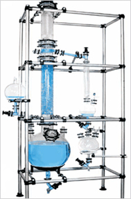
Industrial Glass Pilot System
INTRODUCTION
Standard Units/Assemblies are multi-purpose units having flexibility of utility. These units have been standardized by incorporating all basic & essential features such as heating, stirring, condensation, fractionation, cooling etc. for multi-purpose use. Therefore, though termed “Standard Units” from constructional view point they actually serve as “Flexi Units” from utility point of view.
These units find use in educational institutions, R&D centers and industries. They can be conveniently and quickly modified according to specific process needs due to modular construction. Borosilicate glass offers additional benefits of universal corrosion resistance, visibility and cleanliness.
SIMPLE DISTILLATION UNITS
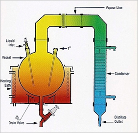
It consists of a vessel mounted in a heating bath and fitted with a condenser for condensing the vapours.
A receiver with drain valve can be added for receiving the condensate.
The units are available in vessel sizes of 20, 50, 100 & 200L and is suitable for operation under atmospheric pressure and full vacuum.
기술사양
| Unit Cat.Ref. | Reactor Capacity | Bath KW | Condenser M2 | Vapour Line |
|---|---|---|---|---|
| SDU20 | 20 L | 4.5 | 80 DN | 0.35 |
| SDU50 | 50 L | 6.0 | 100 DN | 0.50 |
| SDU100 | 100 L | 9.0 | 150 DN | 1.50 |
| SDU200 | 200 L | 12.0 | 150 DN | 1.50 |
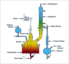
REACTION UNIT
This unit is used for carrying out reactions under stirred condition and with provision for simple reflux distillation.
The reaction vessel is mounted in a heating bath and fitted with addition vessel, motor-driven stirrer and provision for condensation with refluxing. The product is sub-cooled and collected in a receiver.
The units are available in vessel sizes of 20, 50, 100 & 200L and is suitable for operation under atmospheric pressure and full vacuum.
기술사양
| Unit Cat.Ref. | Reactor Capacity | Bath KW | Addition Vessel | Vapour Line | Condenser HTA ㎡ |
Cooler HTA ㎡ | Receiver Size |
|---|---|---|---|---|---|---|---|
| RDU20 | 20 L | 4.5 | 2 L | 80 DN | 0.35 | 0.10 | 5 L |
| RDU50 | 50 L | 6.0 | 5 L | 100 DN | 0.50 | 0.20 | 10 L |
| RDU100 | 100 L | 9.0 | 10 L | 150 DN | 1.50 | 0.35 | 20 L |
| RDU200 | 200 L | 12.0 | 20 L | 150 DN | 1.50 | 0.35 | 20 L |
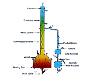
FRACTIONAL DISTILLATION UNIT
This is essentially a compact batch-type fractional distillation unit in which the reboiler consists of a vessel mounted in a heating bath and with a packed column above. The vapours from top is condensed and can be refluxed as per requirement.
The top product is sub-cooled and collected in receivers. The bottom product is finally drained from the roboiler through a drain valve.
The units are available in vessel sizes of 20, 50, 100 & 200L and is suitable for operation under atmospheric pressure and full vacuum.
기술사양
| Unit Cat.Ref. | Reactor Capacity | Bath KW | Addition Vessel | Vapour Line | Condenser HTA ㎡ |
Cooler HTA ㎡ | Receiver Size |
|---|---|---|---|---|---|---|---|
| FDU20 | 20 L | 4.5 | 2 L | 80 DN | 0.35 | 0.10 | 5 L |
| FDU50 | 50 L | 6.0 | 5 L | 100 DN | 0.50 | 0.20 | 10 L |
| FDU100 | 100 L | 9.0 | 10 L | 150 DN | 1.50 | 0.35 | 20 L |
| FDU200 | 200 L | 12.0 | 20 L | 150 DN | 1.50 | 0.35 | 20 L |
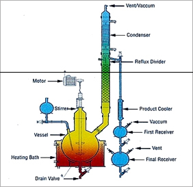
REACTION DISTILLATION UNIT
This is versatile unit and can be used as Reaction Distillation Unit, Fractional Distillation Unit or a combination of both. All features of Reaction Distillation Unit and Fractional Distillation Unit are incorporated.
The units are available in vessel sizes of 20, 50, 100 & 200L and is suitable for operation under atmospheric pressure and full vacuum.
기술사양
| Unit Cat.Ref. | Reactor Capacity | Bath KW | Addition Vessel | Vapour Line | Condenser HTA ㎡ |
Cooler HTA ㎡ | Receiver Size |
|---|---|---|---|---|---|---|---|
| FRU20 | 20 L | 4.5 | 2 L | 80 DN | 0.35 | 0.10 | 2 L 5 L |
| FRU50 | 50 L | 6.0 | 5 L | 100 DN | 0.50 | 0.20 | 5 L 10 L |
| FRU100 | 100 L | 9.0 | 10 L | 150 DN | 1.50 | 0.35 | 10 L 20 L |
| FRU200 | 200 L | 12.0 | 20 L | 150 DN | 1.50 | 0.35 | 10 L 20 L |
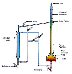
LIQUID-LIQUID EXTRACTION UNIT
Liquid extraction, sometimes called solvent extraction, is the separation of constituents of a liquid solution by contact with another insoluble liquid. The unit described here is for a semi-batch operation.
The liquid to be extracted is poured into an extraction vessel. Solvent is boiled in a reboiler vessel and condensed in an overhead condenser, the condensed liquid collecting in a reflux divider and passing through pipework to the extraction vessel. The pipework incorporates valves in order that the solvent can enter the extraction vessel at either the base of the top, depending on the relative densities of the solvent and liquid to be extracted. The solvent and the extracted liquid pass back to the reboiler and the process is repeated until the extraction is complete.
The extraction vessel is then drained and the solvent evaporated from the reboiler vessel and collected in the extraction vessel enabling the two liquids to be drained from their respective vessels.
The units are available in vessel sizes of 10, 20 & 50L and is suitable for operation under atmospheric pressure.
기술사양
| Unit Cat.Ref. | Reactor Capacity | Bath KW | Vapour Line | Extraction Vessel | Condenser ㎡ |
|---|---|---|---|---|---|
| LLU10 | 10 L | 3.00 | 40mm x 1m | 10 L | 0.35 |
| LLU20 | 20 L | 4.50 | 50mm x 1m | 20 L | 0.50 |
| LLU50 | 50 L | 6.00 | 80mm x 1m | 50 L | 1.50 |
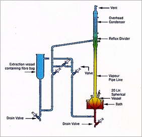
SOLID-LIQUID EXTRACTION UNIT
This operation involves preferential solublising of one or m`ore soluble constituents (solutes) of a solid mixture by a liquid solvent. The unit described here is for a semi-batch operation.
The solid to be extracted is put inside a glass fiber bag and placed in an extraction vessel. Solvent from the reboiler is continuously evaporated, condensed and circulated through a reflux divider by means of piping network and valves. When desired steady concentration of solute is achieved in the solution the operation is discontinued. The solution is drained off and collected for further use.
After charging fresh solid in fiber bag and solvent in reboiler, the cycle can be restarted again.
The unit is available in vessel sizes of 10, 20, & 50L and is suitable for operation under atmospheric pressure.
기술사양
| Unit Cat.Ref. | Reactor Capacity | Bath KW | Vapour Line | Extraction Vessel | Condenser ㎡ |
|---|---|---|---|---|---|
| SLU10 | 10 L | 3.00 | 40mm x 1m | 10 L | 0.35 |
| SLU20 | 20 L | 4.50 | 50mm x 1m | 20 L | 0.50 |
| SLU50 | 50 L | 6.00 | 80mm x 1m | 50 L | 1.50 |
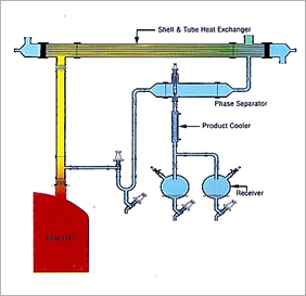
ASSEMBLIES OVER GLASS LINED REACTOR
Glass Lined Reactors are used instead of glass reactors specially when scale of operation is large and relatively high pressure steam is to be used as heating media. Quite often assemblies like Simple Distillation Unit, Reaction Distillation Unit, Fractional Distillation Unit etc. are installed above glass lined reactors. The basic features of these assemblies remain the same but glass shell and tube heat exchanger is preferred due to large scale of operation. A typical fractional distillation unit type assembly over GLR is shown in nearby figure.
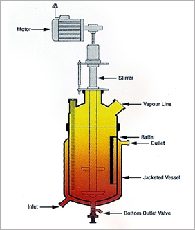
JACKETED REACTOR
Jacketed reactors are similar to glass lined reactors with provision for heating by steam/thermic fluid through the jacket. Transparency permits to visibility. Features like thermometer pocket, motor-driven stirrer, gas sparger etc. are incorporated as per requirement. A baffle battery consisting of 4 baffles can be mounted inside Assemblies like Simple Distillation Unit, Reaction Distillation Unit, Fractional Distillation Unit etc. can be installed above these reactors if required.
기술사양
| Unit Cat.Ref. | Reactor Capacity | DN | Jacket HTA ㎡ | Vapour Nozzle |
|---|---|---|---|---|
| JR5 | 5 L | 150 | 0.15 | 0.35 |
| JR10 | 10 L | 225 | 0.20 | 0.50 |
| JR25 | 25 L | 300 | 0.30 | 1.50 |
| JR50 | 50 L | 400 | 0.60 | 1.50 |
Glass Shell & Tube Heat Exchanger
INTRODUCTION
Shell & tube heat exchangers offer large surface area in combination with efficient heat transfer and compactness. These are widely used in industries for various duties like cooling, heating, condensation, evaporation etc. GOEL are the pioneers in the field of glass shell and tube heat exchangers in India and their product has a wide market acceptability.
SALIENT FEATURES
1. Universal corrosion resistance an excellent alternative to expensive MOCs like graphite, hastelloy, copper titanium, tantalum and other exotic metals.
2. Excellent heat transfer as fouling does occur on smooth glass surfaces.
3. Flexibility of installation vertical/horizontal.
4. Easy replacement of tubes for repair and cleaning.
5. Available in wide range of HTAs.
6. Ease of installation due to light weight.
7. Economical.
8. Suitable for applications where large HTAs are required in limited space.
ADVANTAGES OVER CONVENTIONAL COIL TYPE HEAT EXCHANGERS
(1) The overall heat transfer coefficient in shell and tube heat exchanger is about 3 times higher than in coil type heat exchanger.
(2) The pressure drop in shell and tube heat exchanger is minimal compared to 2-3 kg/cm2 in coil side of coil type heat exchanger.
(3) For requirement of higher heat transfer areas shell and tube heat exchanger is the only answer.
CONSTRUCTION FEATURES
The glass tubes are sealed individually into PTFE tubes sheet with special PTFE sockets and packing. This unique ferrule type sealing arrangement permits easy replacement and cleaning of tubes. Baffles on shell side ensure improved heat transfer by increased turbulence. Further details of construction can be seen in the diagram.
TYPE
Three basic versions * are available :
기술사양
| Material Of Construction | ||||
|---|---|---|---|---|
| Model | Shell | Tube | Header | Duty |
| RGG | Glass | Glass | Glass | For heat transfer between two aggressive media. |
| RGM | Glass | Glass | Steel/FRP | For heat transfer between aggressive media in shell & non-aggressive media in tubes. |
| RMG | Steel/FRP | Glass | Glass | For heat transfer between aggressive media in tubes & non-aggressive media in shell. |
RANGE OF APPLICATIONS
Permissible temperature range for both shell & tube sides -40°C to 150°C
Maximum permissible temperature difference between shell & tube sides 120°C
All sizes & models are suitable for full vacuum on both side. Maximum limiting pressure are tabulated here below :
기술사양
| Maximum Permissible Pressure Range, Kg/㎠ (g) | ||||
|---|---|---|---|---|
| Model | Side | 150DN | 225DN | 300DN |
| RGG | Shell | 2.0 | 1.0 | 1.0 |
| Tube | 2.0 | 1.0 | 1.0 | |
| RGM | Shell | 2.0 | 1.0 | 1.0 |
| Tube | 3.5 | 3.5 | 3.5 | |
| RMG | Shell | 3.5 | 3.5 | 3.5 |
| Tube | 2.0 | 1.0 | 1.0 | |
The above ranges of application are admissible limiting values. For each specific case GOEL recommends the admissible operating data based on the relations between pressure and temperature, size and model.
PERFORMANCE & DESIGN DATA
The particular advantage of shell & tube heat exchanger is high heat transfer performance. The relation between heat transfer and velocity of flow can be easily seen in the diagram. On receipt of the operating data from client the most favorable shell and tube heat exchanger is selected. This accurate design combined with most reliable quality assurance ensures economy and operational reliability for the user.
For approximate sizing some typical heat transfer coefficients are given here below :
기술사양
| U-Value | |||
|---|---|---|---|
| Model | Use | Kcal/㎡ hrk | W/㎡ k |
| Steam water | Condensation | 350-550 | 410-640 |
| Water-water | Cooling | 250-350 | 290-410 |
| Water-air |
Cooling | 30-60 | 35-70 |
고객을 위한 새로운 첨단기술의 만남!
간편한 전화상담 요청
전화번호 입력 후 확인 버튼을 누르시면 관리자가 확인하는대로 빠른시일안에 연락드릴 수 있도록 하겠습니다.
